Devices and Capabilities
Keeping sensors simple.
Two primary types of structural health monitoring sensors work in tandem to detect corrosion and moisture. Our system of sensors, expansion modules, installation options, and interrogation paths is suitable for most new or existing structures. All sensors are passive, battery-free, with no wires to the outside. This ensures a long service life and prohibits external factors entering the structure along a conduit or channel.
Corrosion
detection

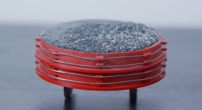
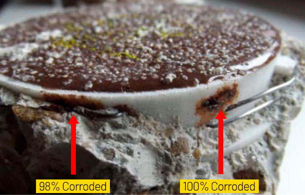
Place corrosion sensors on reinforcing steel before or after pouring concrete. The steel wiring routed around the outside of the sensor body matches the properties of rebar and will be similarly impacted by any corrosive influences that penetrates the concrete.
Two wire layers run around the corrosion sensor. The reader (whether fixed gateway or handheld) obtains an alert when proxy wiring corrodes. The second wire layer allows tracking of the corrosion rate. This is how we determine if the measures taken arrest degradation.
| Diameter | 3.8in / 1.89in (97mm / 48mm) |
|---|---|
| Thickness | 1.02in (26mm) |
| Color | Red / Yellow |
| Body Material(s) | Injection molded plastic + resin |
| Wire Material | S235JR+AR |
| Working Temp. Range | 5F to 131F (-15C to +55C) |
| Measuring Temp. Range | -13F to 131F (-25C to +55C) |
| Measuring R Range | 50Ω to 20 KΩ |
| Lifespan | ≈80 years |
| Install Location | Rebar |
| Power Source | RFID / Induction |
Moisture
detection

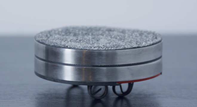
Moisture sensors measure the electrical conductivity and temperature within the concrete. The results are a referenced humidity value as a function of temperature that allows us to understand the concrete moisture profile over its life cycle which can alert you to irregularities in real time.
Conductivity and temperature readings provide the basis for moisture values. The crucial aspect is detecting deviations and anomalies in humidity over time, compared to other sensors in the same structure. With this, we identify abnormal trends and can take early action.
| Diameter | 3.8in / 1.89in (97mm / 48mm) |
|---|---|
| Thickness | 1.02in (26mm) |
| Color | Metallic |
| Body Material(s) | Plastic or Fiber cement + Stainless Steel |
| Working Temp. Range | 5F to 131F (-15C to +55C) |
| Measuring Temp. Range | -13F to 131F (-25C to +55C) |
| Measuring R Range | 50Ω to 20 KΩ |
| Measuring Frequency | 1kHz |
| Lifespan | ≈80 years |
| Install Location | Rebar |
| Power Source | RFID / Induction |
Have questions about our sensor technology?
A collection of frequently asked questions and our answers.
The sensors are very robust and do not contain active electronics. The electronics embedded in the sensors are optimally protected by a thick surrounding layer of epoxy resin, ensuring that external influences such as moisture, stress, etc., do not damage the sensor. The statement about the sensors having a very high lifespan is also based on the principle of energy transfer via RFID. This means there are no cable connections or similar components that can become porous over time and weaken the concrete structure. The lifespan has been demonstrated through MTF calculations by the Fraunhofer Institute. Due to the components used, the probability of failure and the durability of the product were examined, resulting in a calculated lifespan of over 200 years. Since we adopt a realistic approach, we guarantee a lifespan of more than 80 years, analogous to the calculated service life of a concrete structure.
Yes, it is possible to integrate into third-party systems, allowing for monitoring sensors from different manufacturers in one place or using one software solution. The data can be integrated via common interfaces, such as through iFrames into other systems, enriching BIM models with live sensor data, for example.
The sensors were developed in collaboration with Fraunhofer IMS in Germany. They are also manufactured in Germany, highlighting the quality hallmark of “Made in Germany.”
RFID technology is innovative, mature, and durable. The reading of installed sensors can only be done using RFID. The technology on the exterior, such as in the handheld reader and the installed gateways, is always accessible and can be updated as needed. This ensures that data retrieval can be guaranteed in the future.
The sensors can be deployed in any structure where reinforced concrete is utilized. As a result, the sensors are installed in underground parking garages, bridges, port facilities, facades, floor slabs, basement rooms, foundations, wind turbines, insulation, tunnels, retaining walls, and many other objects.
We are happy to assist you with your project plans and provide a complimentary monitoring concept for each object. Prices are available upon request, and we recommend considering the prices in conjunction with a specific project plan as part of a comprehensive concept.
Installation can be provided either by the manufacturer/seller of the sensors or done independently after training provided.
The material of the sensor bodies is a robust hard plastic manufactured by injection molding. The sensors are encapsulated with epoxy resin, and there is a granular layer on top for better adhesion to the concrete. The moisture sensor measures between two stainless steel rings. The wires on the corrosion sensor mimic the rebar using S235JR+AR steel. Through various tests, this wire was chosen for its appropriate material properties and thicknesses.
Important
This is an early warning system that indicates the progression of corrosive activities and informs of their speed so that we can receive information and act efficiently. The aim is not to measure the condition of the reinforcement but to warn of a danger to the reinforcement.
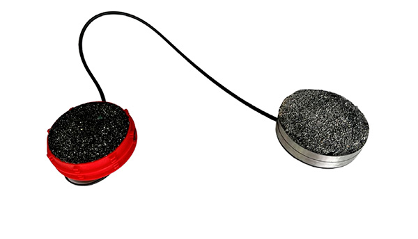
The standard installation depth for moisture or corrosion sensors is limited to 12 in / 30 cm. However, it is possible to achieve a depth of over 328 ft / 100 meters in concrete by using an extended antenna. With the extended antenna setup, the reading unit and the measuring unit are housed in two separate enclosures and connected with a permanent cable link. This allows, for example, measuring at water level in a shipyard while conducting readings from the top of the quay wall. Besides increasing the installation depth, the extended antenna setup can also be utilized to establish reading points, enabling efficient online monitoring with a gateway.

In the rare event that a sensor completely embedded in concrete fails to function, which occurs with a frequency of less than 0.01% due to stringent manufacturing quality standards and thorough sensor-specific quality assurance, a secondary sensor is typically installed near the original sensor using core drilling. The non-functional sensor remains in place as its failure does not compromise or damage the structure.
To prevent microcracks and structural weakening, sensors must have a minimum coverage of 5/8 in / 1.5 cm. In areas without direct load impact (such as vertical mounting in columns), a coverage of 3/8 in / 1.0 cm is sufficient. The material used for covering can be chosen according to the specific requirements of the project.
The data is transmitted directly to the cloud immediately after reading, allowing for immediate access even while on-site at the location. All that’s required is access to InfrastructureTek’s online software, which is provided upon sensor delivery/installation.
The sensors are highly suitable for construction sites and have been specifically designed to withstand high levels of stress. Various tests regarding durability, load capacity, and robustness were conducted beforehand, and the results were documented in a separate report.
| Factor | Influence Level |
|---|---|
| Steel reinforcement (connection with wire tie) | Low |
| Steel reinforcement (welded connection) | High |
| Operation underwater | Moderate |
| Operation under metal-coated sealing | Very High |
| Operation near another RFID Reader | Very High |
| Embedded in concrete | None |
When data is manually retrieved using a handheld reader, it is often done in conjunction with physical and visual inspections of the structure. The frequency of data retrieval depends on the number of manual readings or on-site visits. On the other hand, the gateway continuously transmits data. This means that the data retrieval interval can be customized to suit the client’s needs. It is possible to transmit data daily, hourly, or even every 15 minutes. For more information see our readers and software page.
The gateway can be directly connected to an existing power source, supplied with a long-lasting battery, or operate autonomously via solar panel.
The determination of the required number of sensors does not have a one-size-fits-all answer and is determined on a project-by-project basis. Each structure embodies its unique history, accompanied by individual weaknesses and risk factors.
The economic viability of sensor deployment requires a tailored analysis of each project. The goal is to cover the majority of potential risks with minimal effort. Therefore, positioning sensors at structurally critical points, low points, water drainage areas, seals, and road transitions proves to be of crucial importance. Additionally, the existing damage history of the structure and the applied repair principle play a significant role.
A premature determination, such as assuming 10 sensors per 100 square meters, would be too superficial given this complexity.
There are no specific guidelines for this. It depends on the engineers’ choice of when to trigger the early warning. Some engineers place the corrosion sensor so that the lowest level of the corrosion wire is precisely at the level of the reinforcement to know when corrosion started at that level. However, this does not align with our philosophy of the early warning system. Therefore, the sensor is typically placed directly above the reinforcement, providing information above it. Some prefer to install the sensor as close to the surface as possible to detect trends early.
When the sensor wire corrodes, it is immediately detected during the reading process. With continuous 24/7 monitoring through gateways, proactive alerts are triggered. Because each sensor comprises two wire layers, the advancement of corrosion towards the second wire layer can be monitored. However, once a sensor wire corrodes, it cannot revert to its initial state. It is advisable to conduct a thorough analysis of the location and component using additional diagnostic procedures following wire layer corrosion and establish a focal point for future inspections.

The moisture sensor measures both the temperature in the concrete and the conductivity between the two outer stainless steel rings. The conductivity value is referenced to the surrounding material and the temperature value through the software, resulting in a moisture value in percentage.
Note
Our philosophy is not to be the best and most precise measuring system. We aim to provide a simple and early indication that the moisture level is abnormal and anomalies are visible, allowing for early action before damage becomes visible or expands.
The moisture sensor is tested for functionality in Germany and does not require further calibration. The measurement values are referenced in the software. There are scientific and practical approaches here: Scientifically, the sensor is referenced in the software to the surrounding material in which it is installed, and the software is adjusted accordingly for the most accurate moisture measurement. However, in practice, it is crucial for the moisture sensor’s purposes to detect trends and observe drying or moisture increases. Therefore, the development of moisture trends is more important than knowing whether there is 1.925% or 2.0123% moisture in the structure. Hence, there is the option to adjust the software to the surrounding material, but the trends and early indication of abnormalities are crucial.